Overview
Display Location:
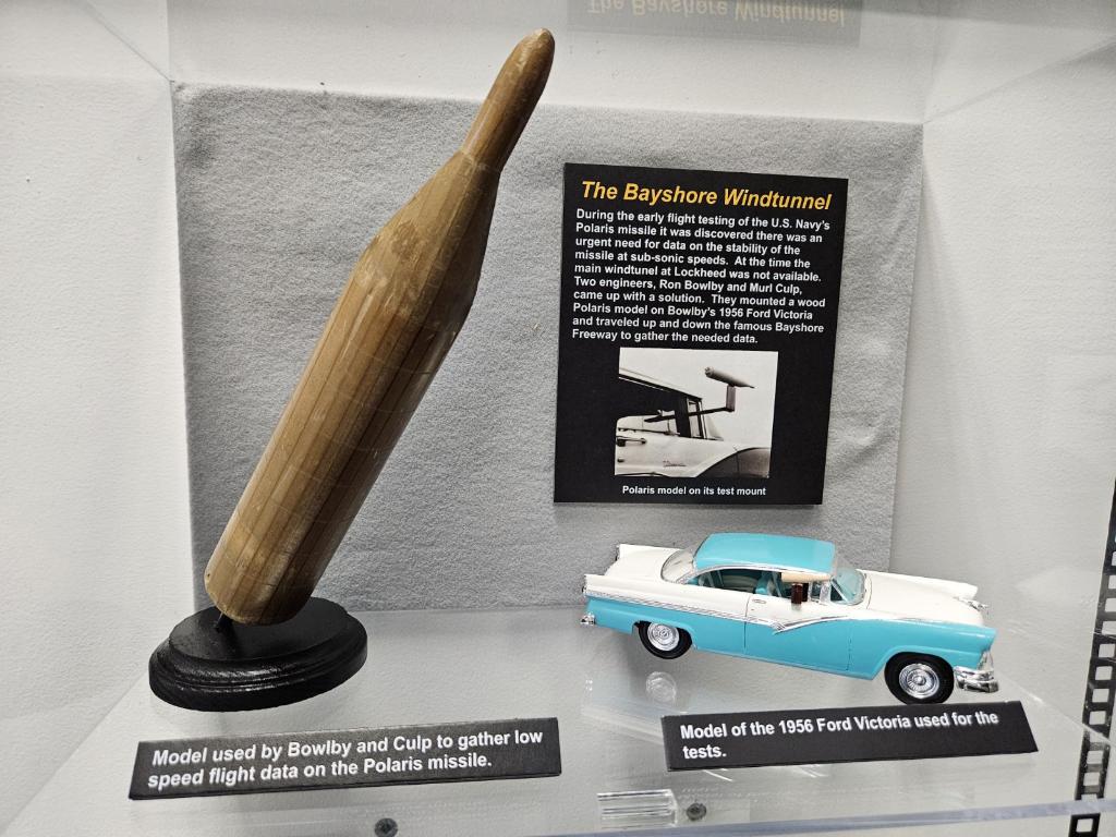
- Sands Space History Center, Cape Canaveral SFS
Composition: Wood
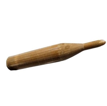
One of the items in our collection is a small wooden model of a Polaris A-1 missile. It doesn’t look like much at first glance, but this unassuming piece of wood played a little known but important part in the development of the U.S. Navy’s first sea-launched ballistic missile system.
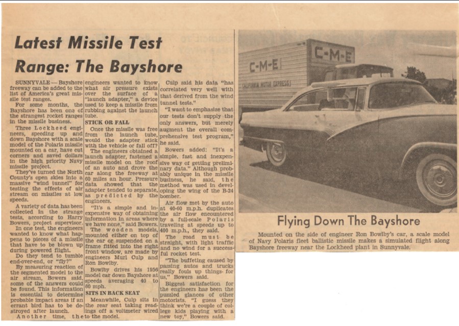
In 1958 Lockheed and the Naval Ordnance Test Unit (NOTU) began flight tests of Polaris missiles at the Cape. The Lockheed engineers quickly discovered they needed additional data on how a shift of the center of pressure on the rocket affected its stability at low (subsonic) speeds. This was important in predicting the possible flight paths of large sections of the missile should it fail and break up in flight.
The easiest way to obtain the needed data was through wind tunnel testing. Unfortunately, the Polaris development team ran into a couple of difficulties when they proposed the test. The first was that Lockheed’s wind tunnel was not available because it was being used for another high priority project. Second, the tests were estimated to run the company around $9,000 dollars (almost $89,000 in 2022 dollars) and with the Polaris program already over budget, Lockheed management felt they could not justify spending the additional funds.
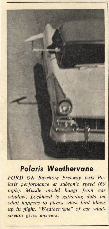
Luckily, two young engineers, Ron Bowlby and Murl Culp, came up with a solution. Working on their own time and with the assistance of technicians in Lockheed’s model shop they built a scale model of the Polaris missile along with a test stand. The entire rig could be secured in the passenger window of Bowlby’s 1956 Ford Victoria. Then the pair would drive down the famous Bayshore Freeway that runs just outside Lockheed’s Sunnyvale, CA plant and gather flight data on the Polaris at subsonic speeds. According to an article in the November 1960 Lockheed Star, “The experiments are usually conducted at 40-60 miles an hour. The air flow over the model simulates the air flow encountered by a full-scale Polaris traveling at speed up to 400 miles an hour”. Engineering reports refer to the car and improvised test rig as the “Rolling Wind Tunnel Facility” or informally as the “Bayshore Wind Tunnel”.
The mount for the model was fitted with a potentiometer attached to a voltmeter. As the wind turned the model, the potentiometer would send a signal to a voltmeter. As the model rotated on its mount, the voltage readings increased or decreased, and from those readings, Bowlby and Culp were able to determine flight angles and the likely trajectories of the parts of a disintegrating missile. That in turn enabled them to better predict the likely impact areas if a missile had to be destroyed shortly after launch.
The “Rolling Wind Tunnel” was used in another test dealing with the Polaris’ launch adaptor. The launch adaptor was a device located on the outside of the missile to prevent it from rubbing against the submarine’s missile tube during launch. The adaptor was designed to fall free after launch, but there was some question as to if aerodynamic pressure would continue to hold the adaptor against the missile, affecting its flight. The rig was modified and after another series of runs down the freeway, the two engineers were able to determine there was no need or concern.
In creating the “Rolling Wind Tunnel Facility” Bowlby and Culp took the initiative and through their ingenuity and creativity were able to gather needed data rapidly and economically (total cost for the program was only $238.00). Their story is only one of many similar stories found throughout the history of the U.S. missile and space programs.