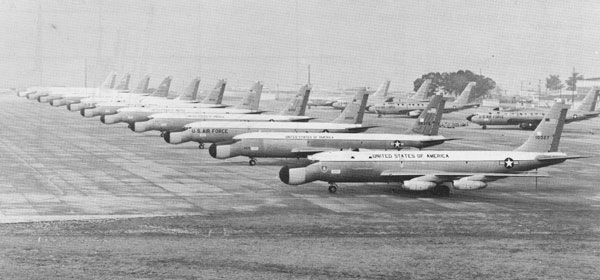
During the Apollo Program, the Patrick Air Force Base flight line hosted these remarkable aircraft. The acronym “ARIA” was defined as “Apollo Range Instrumentation Aircraft.” At the end of the Apollo Program the aircraft received a name change to “Advanced Range Instrumentation Aircraft.” The following information was extracted from a Press booklet printed shortly after the end of the Apollo Program. The booklet explained the reasons for the name change and detailed its specifications. One of these airplanes is on display at the National Museum of the Air Force at Wright-Patterson Air Force Base.
Introduction
In 1962, President John F. Kennedy established an objective for the United States to place a man on the moon by the end of the decade. This objective was met on July 20, 1969, by Apollo 11. When the Apollo program was completed in December 1972, 12 men had set foot on the surface of the moon. The Apollo Range Instrumentation Aircraft (ARIA) contributed to the overall success of the Apollo program.
Since the ARIA’s inception, it has undergone extensive modifications to increase the capabilities necessary for expanding support of manned and unmanned space programs. Because of these changes the present name of this unique aircraft is the Advanced Range Instrumentation Aircraft. It is the intent of this booklet to explain the background, description, instrumentation, and operation of the ARIA.
ARIA Background
In the early 1960’s, the National Aeronautics and Space Administration (NASA) realized that the lunar missions of the Apollo program would require a worldwide network of tracking and telemetry stations, many positioned in remote regions of the earth. The Department of Defense (DOD) was also faced with similar considerations for its unmanned orbital and reentry test programs. Since land stations are obviously limited by geographical constraints and instrumentation ships cannot be moved quickly enough to cover different positions during the same mission, it soon became evident that large gaps in coverage would occur. To fill in these gaps, a new concept in tracking stations was developed a high speed aircraft containing the necessary instrumentation to assure spacecraft acquisition, tracking, and telemetry data recording. The same aircraft could provide coverage for Trans Lunar Injection (TLI) and recovery for NASA’s manned space flight operations, as well as events of interest in the DOD’s orbital or ballistic missile reentry tests.
The airborne station concept became a reality in the form of ARIA. This highly mobile station would be able to operate worldwide, to receive and retransmit astronaut voices, and to record telemetry information from both the Apollo spacecraft and other NASA and DOD unmanned space vehicles. To implement the concept, NASA and the DOD agreed to jointly fund modification of eight C-135 jet transport/cargo aircraft. The ARIA, now designated EC-135N, became operational in January 1968, having been modified at a basic cost of $4 million per aircraft.
The management responsibility of the modification program was shared by both civilian and military agencies. NASA participated in all phases of development and simulation testing. DOD developed policy considerations and assigned overall responsibility for operation of ARIA to the Air Force Eastern Test Range (AFETR). AFETR, in turn, provided test support, personnel, and resources for the operational use of ARIA. All training of ARIA operations and maintenance personnel was accomplished by Air Training Command. McDonnell-Douglas Corporation and Bendix Corporation were the contractors for the design, aircraft modification, and testing of the electronic equipment.
ARIA Description
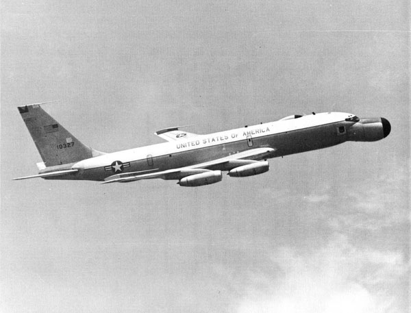
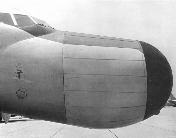
The ARIA fleet consists of eight modified four-engine C-135A jet aircraft. Each ARIA has both external and internal modifications. Externally, the most obvious difference in aircraft appearance is the large bulbous nose. This is a ten-foot radome that houses the world’s largest airborne steerable antenna. The antenna itself is a seven-foot dish, used for telemetry and voice reception in the P-band and S-band frequency ranges.
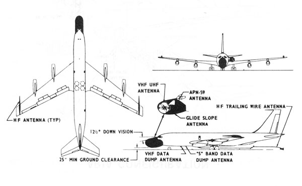
In addition to the “droop snoot” nose, the EC-135N ARIA has a probe antenna on each wing tip as well as a trailing wire antenna on the bottom of the fuselage, all used for high frequency (HF) radio transmission and reception.
Other Modifications
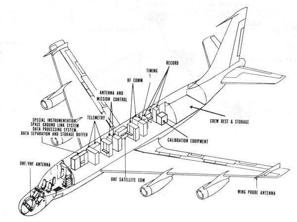
Further external modifications include antennas for post-mission data retransmission and satellite communications. The internal modifications include highly sophisticated state-of-the-art instrumentation subsystems installed in the form of a 30,000 lb. modular package. Also added were facilities for the eight additional crew members who operate the electronic equipment. The basic ARIA specifications and present aircraft configuration are depicted on the following pages.
EC-135N (ARIA) Specifications
| Specifications | |
|---|---|
| Basic Weight | 100,000 lbs |
| ARIA Equipment | 31,640 lbs |
| Water (thrust augmentation) | 5,600 lbs |
| Crew | 2,750 lbs |
| *Maximum Fuel Load | 145,000 lbs |
| *Maximum Takeoff Weight | 285,000 lbs |
| Planning Factors | |
|---|---|
| * Maximum Flight Duration | 10 hours |
| Nominal Altitude | 35,000 feet |
| Cruise Speed | 470 knots (TAS) |
| Range | 4,500 NM |
| Typical Gross Weight | |
|---|---|
| Patrick Air Force Base | 247,000 lbs |
| Guam | 285,000 lbs |
| Hickam Air Force Base | 285,000 lbs |
| Wake | 256,000 lbs |
| Crew |
|---|
| 2 Pilots |
| 1 Navigator |
| 1 Flight Mechanic |
| 1 Mission Coordinator Avionics Officer |
| 7 Electronics Technicians |
| 12 (Minimum Requirement) |
ARIA Instrumentation
The basic function of the ARIA instrumentation system is to receive and record on magnetic tape spacecraft and missile telemetry in the allotted P-Band (225-260 MHz) and S-Band (2200-2300 MHz) frequency ranges. During manned space flight operations, in addition to its receive/record function, the system is also used to perform voice relay between the astronauts and the Johnson Space Center, Houston, Texas.
The telemetry data, in addition to being recorded, may be retransmitted to surface stations either in real-time or post-mission as follows:
- Real-time retransmission of high speed digital spacecraft data to the Range User via available DOD communications satellites and existing ground stations. This allows the instantaneous analysis of critical events as they occur on-board the spacecraft.
- Real-time retransmission of analog or low speed digital data to the Range User via HF radio, also allowing continuous monitoring of selected spacecraft parameters.
- On-board readout of selected spacecraft parameters for voice report to the user via HF radio.
- Post-mission transfer of one or two tracks of recorded data to a ground station, within line of sight of the aircraft, via VHF and UHF transmitters. The ground station may then send the data to the user through existing channels, allowing him access to ARIA data several days in advance of the actual delivery.
- Post-mission reception and recording of an instrumented ship’s data, thereby speeding up the delivery of its data to the user.
Electronic Subsystems
Three electronic subsystems and a master control console contain the Prime Mission Electronic Equipment (PMEE) which provide the ARIA mission support capability. These subsystems are as follows:
a. VOICE AND TELEMETRY SUBSYSTEM.
This includes the Antenna Group Radio Frequency (RF) Group and the Record Group.
1. The Antenna Group acquires the spacecraft and maintains track using the seven-foot dish antenna to receive the P-band and/or S-Band signals radiated by the spacecraft. The antenna may be either manually pointed to the target or will track automatically if adequate signal strength is present. From the antenna, the signals are routed to the telemetry receivers in the RF Group for processing.
2. The RF Group consists of the receivers required to process the received UHF and VHF spacecraft signals for telemetry and tracking information, the transmitters and receivers needed for spacecraft communications during manned space flight missions, and ancillary equipment used for calibration, group interface, and data transfer operations. Additionally, a special equipment rack can be installed on each aircraft to allow reception and processing of Space Ground Link Subsystem (SGLS) signals, a standardized telemetry format used frequently in USAF missile operations.
An important extension of the voice and telemetry subsystem is the equipment which can be installed to provide real-time retransmissions of spacecraft telemetry signals. Following processing by special components in the SGLS rack, the data is routed to the HF equipment area where, depending upon individual mission requirements, it will be transmitted via either communications satellite (UHF) or HF radio to the appropriate user agency. ARIA’s real-time data capability has played a continuously increasing role in the U. S. Space Program and should continue to do so in the future.
3. The Record Group uses standard equipment to meet ARIA requirements for data storage, monitoring, and playback. The primary components of the group are two M-28 wideband magnetic tape recorders, each capable of recording 14 tracks of data on 9200-foot reels. At 120 inches per second, the units offer 15 minutes of recording time with a bandwidth of 5 KHz to 1.5 KHz in the direct record mode and DC to 500 KHz in the FM record mode. While separate tape tracks are used for each channel of telemetry data, timing codes, receiver signal strengths, voice communications, and other low frequency signals are all multiplexed before recording to conserve tape space.
b. TIMING SUBSYSTEM.
The Timing Subsystem is a central timing facility for the ARIA electronic system. Its primary function is to generate time codes and precision pulse repetition rates which are recorded with the data to allow for time correlation in interpreting spacecraft events when the tapes are processed. In addition, the subsystem provides each equipment operator with displays of -Coordinated Universal Time (UTC) and mission countdown/elapsed time. Using a Rubidium frequency standard as the primary signal source, the system is capable of providing accuracy of plus or minus 5 milliseconds when referenced to National Bureau of Standards timing broadcasts on HF radio (WWV or WWVR) or better than one microsecond referenced to an external synchronization source.
c. HF COMMUNICATIONS SUBSYSTEM.
The HF Communications Subsystem provides voice and teletype communications through any of three 1000 watt single sideband HF transmitters and receivers. The units are tunable over 280,000 discrete frequencies in the 2 MHz to 29.999 MHz frequency range and are capable of simplex or full duplex operation. Additional communications capability is available when a satellite terminal is installed in the HF position, allowing voice communications and/or data retransmission via communications satellites as previously described. The primary purpose of the HF Communications Subsystem during normal operations is to provide liaison with Aircraft Operations Division (AIROPS) at Patrick AFB for flight following and mission update during aircraft deployments.
During manned space flight operations, the HF position also serves as the interface between ARIA’s spacecraft communications equipment and the HF net to the ground. The aircraft receives uplinks from Houston through an HF ground station and retransmits the voice to the spacecraft via UHF and VHF transmitters. Astronaut downlinks are received simultaneously by VHF and UHF receivers, then the best of the two sources is selected for HF “remoting” to the ground.
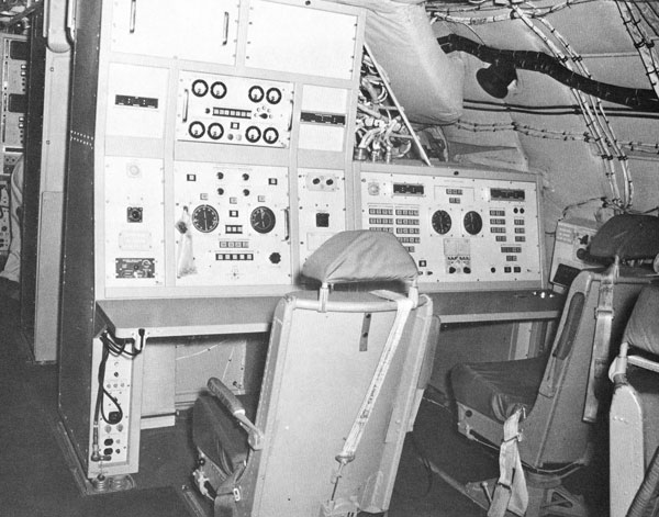
On-board supervision of the instrumentation crew during a mission is the responsibility of the ARIA Mission Coordinator. The MC operates a master control console in the instrumentation area where he monitors the status and operation of all ARIA subsystems and initiates commands to the equipment operators under his direction. He is the interface between the aircraft and AIROPS for coordination of mission related information, and also serves as the point of contact between the flight crew and the instrumentation crew.
Modifications
Periodically mission requirements evolve which cannot be met with existing ARIA instrumentation, necessitating modification of the basic system. Over the years, a number of these have been performed, increasing overall ARIA capabilities and greatly enhancing its ability to support a wide variety of missile operations. The SGLS support and real-time data retransmission capabilities previously mentioned are examples of ARIA modifications which have been used extensively since their development. Other modifications have been performed to allow support of R&D testing in the Navy’s Trident program, the Army’s Airborne Bistatic Receiver Program, and other missile operations involving frequencies and support requirements which are not normally encountered.
ARIA Operations
The Air Force Eastern Test Range is responsible for maintenance and logistic support of the ARIA fleet throughout the world, regardless of the operating base. AFETR’s Aircraft Operations Division is responsible for the mission planning, crew manning, and direct command and control of ARIA during mission deployments. During actual mission operations, a support team is on duty at AIROPS to control aircraft activities and provide an interface between the mission control facility and the ARIA fleet. During manned space flight operations, AIROPS serves as an integral part of NASA’s Spaceflight Tracking and Data Network (STDN) and during mission support periods responds to the requirements of the Johnson Space Center in coordinating and directing ARIA support operations.
Normal mission support begins with a two-day aircraft Pre-Mission Calibration (PMC) at Patrick Air Force Base. The PMC consists of several checks which ensure that all electronic subsystems are operating within specifications and configured properly to meet specific mission requirements. Following PMC, mission support aircraft may depart Patrick Air Force Base up to seven days prior to a scheduled launch to arrive at their staging bases a minimum of twenty-four hours prior to support.
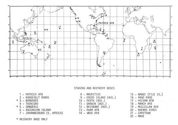
Since the ground tracks of space and/or reentry vehicles launched from the Eastern and Western Test Ranges may encompass a large portion of the earth’s surface, and events of interest onboard the vehicle often occur outside the coverage limitations of existing surface stations, ARIA operations are truly worldwide in nature. The map on the following page displays a number of the staging bases which have been used for ARIA support, which is normally over the broad ocean area.
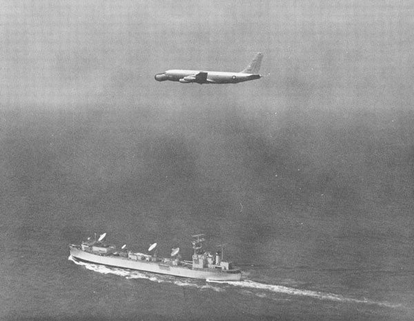
On the day of mission support, ARIA customarily depart their respective staging bases two to three hours prior to liftoff and proceed to their test support areas, performing a final PMEE systems verification enroute. Following missile liftoff, the aircraft commence their “data runs,” proceeding along a specific course and reaching a predetermined test support position (TSP) at a precise time. Throughout the mission, communications are maintained with AIROPS via HF radio through a worldwide HF communications network which stretches from Cape Canaveral east to the Indian Ocean and west to the Western Pacific.
Following support, the aircraft are returned to Patrick Air Force Base, where their magnetic tapes are processed for the desired vehicle data.
Among the programs which have received ARIA support are those depicted on the following page. The list encompasses a wide variety of technical requirements and support plans, and should point out the versatility of the ARIA system. The aircraft have been and continue to be in constant demand by both military and civilian agencies.
We hope this booklet has satisfactorily explained the ARIA system, its use, and its ever-increasing role within our nation’s space program.
ARIA Project Support
NASA
- APOLLO
- SKYLAB
- PIONEER
- MARINER VENUS MERCURY
- MARINER MARS
- WESTAR – A
- SMS – A
- INTEL SAT
- IMP
- SKYNET II – A
- ATS-F
- AE – C
- HAWKEYE/NPE
Department of Defense
- POLARIS
- POSEIDON
- TRIDENT
- MINUTEMAN I, II & III
- ATHENA
- ABRES
- PERSHING
- SRAM
- HEART (DNA)
- TITAN III-C
- CLASSIFIED OPERATIONS